Modern Energy Rental Pvt. Ltd. - An Energy Rental Organization.

Knowledge Bank

Knowledge Bank

  • Home
  • /
  • Knowledge Bank

01.SAFETY GUIDELINES

  1. Personnel engaged in the DG Set Installation, commissioning, operation and maintenance must be competent and experienced in these fields. They must also be conversant with all relevant, current statutory requirements and local regulations. Before installing the DG Set, read this manual carefully to get familiar with the equipment and its operation. (Including all systems and controls, manually operated valves and shut down devices). Correct DG Set installation, operation and maintenance is essential for safe and efficient operation. Many accidents result from a failure to observe fundamental safety rules and precautions.
  2. There are many potential hazards that can occur during operation of DG Set which cannot always be anticipated. Therefore a warning cannot be included in this manual for every possible circumstance that might involve a potential hazard.
  3. While unloading, shifting of DG Set please ensure proper care is taken so that no damage to men and material is done. Please use proper unloading equipment’s, tools and tackles.
  4. DG room should have proper escape routes. An escape map may be displayed in the DG room which should be clearly visible to all would be helpful during any accident or fire.
  5. Please provide proper Fire Extinguishers in DG Set room area.
  6. Please put Hazard Signs for Electricals Panels, Fuel and Lubricants etc.
  7. Personal Protection gadgets like -Safety hand gloves, goggles and ear plugs for protection of all operators, engineers and staff would make them safe, while working in DG Set room.
  8. Ensure proper guards / protections for all moving parts.
  9. Use of proper tools and tackles is recommended in the DG Set Room.
  10. Electrical cables are fire Hazards during short circuits / failures – Please take proper care while routing of cables particularly power cables.
  11. DG Set exhaust gas temperature will be about 450-550 Deg. centigrade and exhaust pipes need proper cladding and insulation.
  12. Ensure there is no fuel and lubricating oil leakages in the DG set room, as they are fire Hazards.
  13. Diesel Fuel handling need proper care, as they are also fire hazards.
  14. Please ensure proper care is taken while lifting Heavy parts of the DG Set. The capacity of the lifting cranes should be suitable.
  15. Earthing of the DG Set is recommended and please refer to the specific recommendations.
  16. Keep tools & other metallic objects away from uncovered batteries. Use tools covered with vinyl electrical tapes or suitable non – conducting material to avoid possibility of shorting battery connections while working near batteries.
  17. In case of bulk diesel storage and liquid gas storage, proper signage like “’NO SMOKING’ boards should be prominently displayed.
  18. Engine lubricating oil, engine coolant and grease are to be disposed at site as per site regulation requirement and considering MSDS (Material Safety Data Sheet).
  19. Engine consumables replaced during maintenance like filters, are to be disposed at site as per site regulation requirement.
  20. Batteries are to be disconnected, in case of persons working on the DG Set.
  21. Disconnect all harness connections to the PCC & Engine control system before doing any welding work on DG set. Controller & PCB can get damaged due to welding currents. DG Set starting batteries to be disconnected at battery end before any welding work or maintenance.
  22. During transportation of DG set with AVMs in-between sub base and engine generator ensure AVMs have shipping brackets (solid restraints) to prevent transit damage. Ensure to remove the shipping bracket before starting the DG Set.
  23. Safety lockout and tag out process to be followed during maintenance.

02.DG SET INSTALLATION RECOMMENDATION

A. LOCATION

Following options are applicable for DG set Configuration.
i. DG set with Acoustic Enclosure in open Area. (Refer Sketch. A-I)
ii. DG set with Acoustic Enclosure in covered Area. (Refer Sketch. A-II)
iii. Open DG set in Room Acoustic. (Refer Sketch. A-III, Sketch 3A & Sketch 3B)

A.1 D.G Set should be located considering ventilation air requirement as indicated in the Section.
A.2 Wherever possible position the DG set so that the prevailing wind do not enter into the radiator/exhaust outlet. If this is not possible, install a wind barrier. Refer sketch A.2

A.3 DG Set should be located away from polluted atmosphere like coal dust acidic fumes, cement dust, stone dust cotton fibers, furnace chemicals etc. wherever possible.
A.4 In case of dusty locations (such as stone crusher, construction sites, cement industries, etc.) Necessary air suction filters at canopy, sand louvres needs to be considered as per site requirement.
A.5 For humid / coastal atmospheric applications, space heaters are mandatory for alternator.

A.6 Spacing Guidance

No. Description DG set with Acoustic Enclosure in Open Area. DG set with Acoustic Enclosure in Covered Area. Open DG set in room.
1 Free space on both sides Min. 1.5 m Min. 1.5 m Min. 2 m
2 Free space at front side (Radiator- – Hot air outlet at front) Min. 3 m Min. 3m (with ducting to avoid re-circulation) Min. 1.5 m
3 Free space at front side (Radiator- Hot air outlet at top) Min. 1m Min. 1.5m N/a
4 Free space at rear side (Alternator) Min. 2 m Min. 2 m Min. 2 m
5 Fresh air inlet opening area N/A N/A Min 1.5 times of the Radiator area.
6 Hot air discharge opening area N/A N/A Min. 2.5 times of the Radiator area.
7 Distance between two sets Min 1.5m between two canopies Min 1.5m between two canopies Min 1.5m between two foundations.

N/A – Not applicable

B. ROOM LAYOUT (FOR OPEN SETS WITH ROOM ACOUSTICS)

B.1 While making room layout due consideration should be given for accessibility, serviceability of

  • Cable
  • Fuel lines
  • Breather vent
  • Coolant /lube oil drain
  • Raw water lines
  • Heat dissipation
  • Hot air discharge
  • Removing skin heat
  • Removing Alternator

Note: Breather vents should be necessarily taken out of the DG Set room or Acoustic enclosure as applicable
ROOM LAYOUT IS IMPORTANT FOR:

  • Performance, Serviceability, Ventilation, Ease in operation and Electrical safety.
  • DG Set room aesthetics

B.2 Future expansion plans should be considered while deciding room size.
B.3 Enough opening should be provided to the DG set room so that entry and placement of DG set is easily possible.

C. ROOM VENTILLATION

C.1 Ventilation of the generator room is necessary to remove heat and fumes dissipated by the engine, and alternator and its accessories and to provide clean and fresh air. Ventilation requirement is mandatory for all engines. (Refer table no.1)
IMPROPER VENTILATION CAN LEAD TO:

  • Poor performance and reliability of DG Set
  • Poor fuel efficiency
  • Premature failures of engine, alternator and electrical components.
  • Unbearable working conditions due to higher room temperatures.

C.2 For DG set mounted radiator installation, natural adequate air is required for satisfactory operation of DG set. Air should flow from alternator end to engine (For forced ventilations contact OEM / Cummins). Refer Sketch C.2

C.3 Additional ventilation arrangement may be required for radiator cooled engines installed in acoustic rooms. Typical arrangement is shown in sketch 3A above.
C.4 Typically the hot air removal fan should operate only after the DG is stopped to take away the heat from room area and also to prevent short circuiting of fresh and exhaust air. For heat exchanger cooled engines, the forced ventilation system is required. This can be achieved by,

Option – A
Providing natural air from rear side of DG set and hot air exhaust thru axial flow fans from front side of DG set.

Option – B
Providing forced air thru axial flow fans at rear side of DG set and hot air outlet through louvers provided at DG front area.

Option – C
Providing forced air thru axial flow fans and hot air exhaust through axial flow fans. Exhaust fan capacity should be less than 70 to 75% of fresh air supply fan capacity.

In all cases care should be taken to avoid re circulation of hot air. In some cases, it may also be achieved by natural wind direction consideration.

Note: Refer Table 1 for Ventilation air quantity requirement.

i) Fan flow rate should be selected according to the engine breathing air and radiation heat dissipation with permissible temp rise in DG room/Enclosure.
ii) Static head of the fan should be selected according to the restriction at air suction area and hot air outlet area, also consider the attenuation requirement.

C.5 Maximum temperature allowed to rise in DG Set room is:

Max. Ambient Allowable temp. rise
Up to 40oC 10oC
40 to 43oC 7oC
Above 45oC 5oC

Note: For Engine mounted radiator installation, typical temperature rise is about 7 oC

Formula for Ventilation Air Quantity Calculation

Option-1 – Air flow quantity requirement in CFM

Where H is heat load in btu / minute and Δ T in Degree Fahrenheit.
Engine combustion in CFM.

Option- 2 – Air flow quantity requirement in m3/ Minute

Where H is heat load in kW and Δ T in Degree Centigrade.
Engine combustion in m3/min

C.6 Field check for proper ventilation

  1. Run the DG Set on full load / typical load for about 1 hour so that temperature in the DG Set room gets stabilized.
  2. Measure the ambient air temperature (ambient temperature should be measured outside the DG Set room in shade).
  3. Measure the temperature inside the DG Set room. DG Set room temperature should be measured near air cleaner inlet of engine.
  4. Calculate temperature difference between DG Set room temperature and ambient i.e. delta T.
  5. To ensure proper ventilation, it may be necessary to measure actual airflow by anemometer.

D. FOUNDATION

D.1 Do not install DG Set on loose soil or sand clay, unless kept temporary.

Typical DG Set foundation drawing is given above for reference.

D.2 Foundation should be designed considering safe bearing capacity of soil and DG set static and dynamic load. Anti-Vibration Mounts (AVMs) are provided to reduce generator set vibration and noise transmission to the surrounding structure.

D.3 The depth of the foundation to be decided by the customer in consultation with the certified structural engineer depending on static and dynamic load of the DG set and soil condition. Contact GOEM for static and dynamic load data of the DG Set

D.4 The length and breadth of foundation should be minimum 150 mm (6”) more than acoustic enclosure size / base rails size

D.5 Ensure that the concrete is completely set and hardened before positioning the generator set.

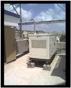
D.6 It is recommended to have foundation elevation 150 mm above finish ground level. It helps to maintain cleanliness of DG Set. For areas having heavy rainfall, a higher platform/ rain shed (not mandatory) may be required to prevent water entry and it also helps in operator’s safety.

D.7 DG Set foundation level to be checked with water level tube at frame mounting area and should be within +/- 5mm for 750 kVA and above DG Set. For DG sets below 750 kVA +/- 2.5mm to be maintained. Metal shims to be provided between DG frame and civil foundation to load DG Set uniformly.

D.8 The AVM’s of DG Set should be loaded uniformly for DG sets where AVM’s are placed on foundation & below DG set base frame. Use shims below AVM resting area. Shim plate should be of 3 mm minimum thickness and to be used in multiple as required. Ensure that AVMS are loaded evenly.

D.9 It is recommended to take services of your structural Engineer for designing foundations and carryout seismic analysis if required.

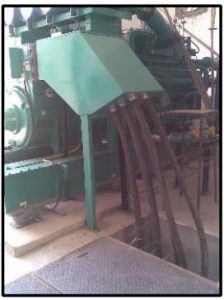
D.10 For cable laying, necessary civil trench to be considered in civil works as per site requirements. In case of cable termination at the top/ bus duct, the trench is not required but necessary supports to be considered.

D.11 In case of special requirement, civil foundation to be casted in isolation with building structure.

D.12 DG Set with integral vibration isolators can reduce vibration transmitted to foundation by @80 %.

D.13 Special conditions for seismic zone to be considered while selection and installation of DG set. Contact GOEM for details.

D.14 Guidelines for Installation of Low kVA DG set. (7.5-62.5 kVA)

  • DG sets location area / foundation should be capable to bear the STATIC load and
    DYNAMIC Load which is typically 2.5 times the static load during running.
  • Raise level by 150 mm above finish floor to ensure that the Rain water does not enter the acoustic enclosure and rust the base/base rail.
  • There are various options where we can either install the Acoustic enclosed DG Set.
  1. Re-enforced floor (See Option 1)
  2. Create a structure from the base civil structure (See Option-2).

E. UNLOADING

E.1 Provision for DG Set lifting is provided on base-rail/enclosure. Unload the DG Set from the base rail/enclosure by lifting with proper DG Set lifting tackle or nylon sling /steel rope of suitable capacity and crane so as to ensure no damage to oil sump, air cleaner, radiator pipes etc.

E.2 Do not lift the DG Set from engine and alternator hooks. These are designed for lifting individual items only.

E.3 Keep the DG Set covered with polyethylene or tarpaulin during installation to ensure that water does not enter inside.

E.4 Spreader bar / spacer plate of suitable size must be used to avoid damages to DG Set components. While unloading/ shifting of DG set.

F. AIR SYSTEM

F.1 Vacuum indicator is supplied with all engines to indicate air filter condition (choking). Max air intake restriction with clean and choked filter is given in the below table:

Procedure to check air restriction

Run the engine at Rated RPM and Rated load and connect/record restriction on water manometer as below: Refer Sketch F.1

F.2 Higher restrictions leads to:

  • Air filter rupture
  • High fuel/lube oil consumption
  • Low power
  • Black smoke
  • Turbo charger failure

F.3 In case of dusty locations (such as stone crusher, construction sites, cement industries, etc.) Necessary air suction filters at canopy, sand louvres needs to be considered as per site requirement.

F.4 If fibrous conditions exist then care should be taken to prevent the fibers from getting sucked into the air cleaner. Provide air ducts, air curtains, nets etc. In such cases consult OEM / Cummins.

F.5 Care to be taken, that no such fiber element shall enter/ block the air flow of alternator.

G. EXHAUST SYSTEM

G.1 Well-designed exhaust system collects exhaust gases from engine cylinder and discharges the as quickly & silently as possible. External exhaust system should be designed to have minimu back pressure and restricting it to within limits as below for that particular engine model to ensu maximum efficiency. This is therefore of at most important that we do it with minimum and s bends. It is desired to have exhaust pipe routed upwards for easy removal of exhaust gas. (Ref Table G.1)

EXHAUST DUCT DIAMETER SELECTION/CALCULATIONS FOR DG SETS

S n Engine Model Model DG Set Ratin g Prim e kVA Total Exhaust gas flow for DG Set m3/s Exhaust silence r No. per DG number Recommended Exhaust duct dia. After each turbocharger – inch Calculated exhaust gas velocity in m/s for duct after turbo m/sec Recommended exhaust duct dia. – Common after Y-piece – inch Calculated exhaust gas velocity in m/s for common duct after y-piece m/sec
1 KTA38G5 1010 2.92 2 10 29.95 12 41.60
2 KTA50G3 1250 3.82 1 10 39.15 14 39.95
3 KTA50G8I 1500 4.44 2 12 31.60 16 35.54
4 QSK50G10 1800 5.13 2 12 36.57 16 41.15
5 QSK-60-G3 1875 5.39 2 14 28.22 18 34.14
6 QSK-60-G4 2000 5.60 2 14 29.33 18 35.49
7 QSK-60-G8 2250 6.31 2. 14 33.05 18 39.98

Table G1

G.2 Higher exhaust back pressure leads to

  • Lower fuel economy
  • High exhaust temperatures and related failures
  • Poor performance of the engine
  • Less durability of the engine

LIMITS FOR EXHAUST BACK PRESSURE
The exhaust back pressure should not exceed the limits in below table. Exhaust velocity of typical 35 40 m/sec is often suitable, but depends on actual pipe configuration. Refer Table G.2 for permissib pressure drop in exhaust system.

Model mm (inches) of Hg kPa
X1.3 30.98 (1.22) 4.13
X2.7/ X3.6 29.97 (1.18) 4
6B5.9 38.1 (1.5) 5
4B3.3/ 4B3.9/ 6B5.9/ QSB5.9/ QSB6.7/ QSL9/ QSN14/ KTAA19/ KTA38 76.2 (3) 10.15
QSK 19/ K50/ QSK50/ QSK60/ QSK78 50.8 (2) 6.77
Gas Engines 50.8 (2) 6.77

Table G.2

For new installations, it is recommended to have 20% minimum design cushion in calculated back pressure value and permissible limit ( as specified in Table G2).

G.3 Use of thimble is must while passing the pipe through concrete wall. The clearance around the pipe in wall is must, for free movement and expansion.

G.4 Exhaust piping inside the DG Set room must be insulated with minimum 50 mm thickness with 64 kg/m3 density of rock wool wrapped with 24/26SWG aluminum sheet cladding to minimize heat radiation inside the DG room. Approximate heat radiation after insulation will be about 1 KW per meter length of exhaust pipe.

G.5 Exhaust flexible shall have its free length when it is installed. Recommended piping arrangement with support locations for engine is shown in below sketch. Additional bellow/s to be provided in horizontal exhaust pipe line after every 6 to 10 meter considering axial movement of 30 to 40mm and lateral movement of 10 mm, which is recommended. It is important that thermal fluctuations is minimized by proper use of flexible as well as rigid suspension points. One sturdy fixed point support must be provided for be expansion bellows on the turbocharger. It should be positioned immediately above the expansion bellow in order to prevent transmission of forces resulting from weight, thermal expansion or lateral expansion of the exhaust piping to the turbocharger. Flexible bellows to be provided after exhaust silencer also. Refer Sketch G.5 below.

G.6 Please refer backpressure nomograph for calculating exhaust piping back pressure & sizing calculation, as per site exhaust ducting layout scheme. i.e. length, bends, bellows, horizontal and vertical ducts and refer sketch G.6 for back pressure measurement location. In addition one can make use of Exhaust Calculators available with team Cummins.

Calculations for Equivalent Pipe Length Nos. EQ length in meter Total length in m meter
Straight pipe – meter 1.0
90 deg. standard elbow – nos. 1 7.9 7 9
90 deg. medium radius elbow – nos. 1 6..7 6.7
90 deg. long radius elbow – nos. 1 5.2 5.2
45 deg. elbow – nos. 1 2.4 2 4
Tee, side inlet or outlet – nos. 1 17.1 17.1
18 inch. flexible tube – nos. 1 0.9 0.9
24 inch. flexible tube – nos. 1 1.2 1.2

G.7 Rain protection to be provided for exhaust ducting like, 90 deg. bend with bird mesh, cowl or special diffuser. It is recommended that horizontal run of exhaust piping should slope downwards away from the engine. Condensate drain pipe to be provided in horizontal ducting after silencer to avoid rain water entry or condensate entry to engine.

G.8 Silencer Location: Locating the silencer close to the Engine improves the sound attenuation.

G.9 Exhaust stack height: In order to dispose exhaust above building height, minimum exhaust stack height should be, as per latest CPCB/ local pollution control board norms.
a. For DG set below 800 kW
H = h + 0.2 x √kVA
Where H = height of exhaust stack h = height of building.

b. For DG set above 800 kW
– Minimum 30 meter

c. In case building height is more than 30 meter
Stack Height = Building height + minimum 6 meter.

Note: Exhaust stack height should be considered of maximum value of the above.

G.10 Recommended scheme for ‘Y’ piece construction for two banks duct connections:-
Exhaust of two banks of V engines can be connected before/after silencer. Ensure that the common duct diameter is calculated considering the backpressure and velocity criteria.

COMMON EXHAUST SYSTEM FOR MULTIPLE DG SETS NOT RECOMMENDED
G.10 Common exhaust system for multiple DG sets is not recommended due to condensation issue, possibility of exhaust gas entry to non-working engine and lack of failsafe system availability. However exhaust of two banks of V engines can be connected before/after silencer. Ensure that area of common pipe is greater than sum of the areas of individual pipes.

G.11 In case of special requirement of common chimney or in case of Heat Recovery System contact Cummins / GOEM.
The following critical points to be taken care

  1. Individual DG set exhaust duct diameter to be selected as per back pressure and exhaust velocity criteria.
  2. DG set duct entry to stack should be at an angle of 45 deg. max (w.r.t. vertical stack pipe)
  3. There should be minimum 1.5 meter space between two duct nozzles connected to vertical stack.
  4. DG Set duct should be protruded in the vertical stack by about 25mm.
  5. Condensate drain point should be provided for each DG set horizontal duct laid before stack entry.
  6. Stack pipe diameter to be selected as per back pressure and exhaust gas velocity considering all connected DG sets in operation.

G.12 Installation of wet scrubber in DG exhaust as per site requirement: In case of exhaust wet scrubber requirement as per site regulation, following points to be taken care:
I. Exhaust back pressure is within the prescribed limits.
II. The maintenance of the scrubber needs to be carried as per the recommendations of the manufacturer.
III. Necessary precautions to be taken in exhaust scheme design to avoid condensate/steam back entry to DG sets which is/are not in operation.

H. FUEL SYSTEM

a. Diesel Fuel System
Diesel Fuel specification should as per IS 1460 (HSD No.2 diesel). For details specs refer Operation and Maintenance Manual.

H.1 Fuel supply and return line restriction for fuel system, refer operation and maintenance manual, HIGHER FUEL RESTRICTION LEADS TO:

  • Lower power
  • Late stopping
  • Engine die down

H.2 For DG sets of rating up to 700 kVA the fuel tank is in sub-base type part of DG Set skid. For DG sets above 750 kVA, 990 lit capacity day tank is supplied loose, which needs to be installed at floor level or 300 mm above the DG floor level to maintain positive suction head on fuel pump inlet.

The height of the day tank should be sufficient to put a positive head on the engine fuel pump. (Minimum level in tank not less than 6 inches [150 mm] above engine fuel inlet.) The maximum height of fuel in the day tank should not be sufficient to put a positive head on the engine fuel return lines. Please ensure that all diesel lines are leak proof and should prevent air seepage even if the DG sets is not run for a long time.

H.3 FUEL TANK DESIGN

  • Size to suit at least one shift operation or maximum 990 litters. (Material MS for fuel tank and piping).
  • Drain fittings to bleed water condensate at lower point of tank.
  • Fill neck to be provided to allow min. 5% expansion space.
  • Breather is mandatory.
  • Use pipe sealant Loctite Type 577 for all connections, for sealing. No teflon tape to be used.
  • Suction and return line to be separated by at least 300 mm.
  • Galvanizing not recommended inside fuel tank. Hand hole, Wire mesh filter screen at fillers point.
  • Providing Hand hole for cleaning and wire mesh filters screens at filler points is mandatory.

H.4 C.S. seamless pipe schedule 40 should be used for fuel piping from fuel tank up to the engine. Fuel tank up to the engine Flexible hoses supplied with the engine should do the terminal connection between MS pipe and engine. (ERW pipes are not allowed)

H.5 Fuel piping should be free from leaks. GI and copper pipes react with diesel and can’t be used.

H.6 Please refer table 1 for recommended fuel line sizes for fuel piping lesser than 10 m. If piping length is more than 10 meters, contact OEM / Cummins.

H.7 Fuel tank location should be such that it doesn’t restrict movement of service personnel or block flow of ventilation air.

H.8 System in enclosure are pre-validated. One only needs to take exhaust out to a safe area and provide adequate ventilation

H.9 Contact GOEM for design/supply of bulk diesel storage tanks as per Chief Controller of Explosives (CCoE).

b. GAS GENSET FUEL SYSTEM RECOMEMNDATIONS

Whilst most of the installation guidelines discussed for diesel products can be used while installing the gas engine(s), it is necessary to have a brief overview of the various components used in the gas supply line prior to getting connected to the gas engines.

Various components used in gas supply piping to the engine inlet and installation recommendations are as follows:

The fuel system for gas engine includes following:

  1. Manual shut-off valve (Main line Valve)
  2. Gas Filter
  3. Gas shut-off valve (Electrical)
  4. 1st stage regulator
  5. 2nd stage regulator
  6. Carburetor

Note: Please do proper earthing of complete gas train. It is recommended to use copper wires to loop between two flanges. Also one earthing wire should connect engine and gas pipe train.

1. MANUAL SHUT OFF VALVE (MAIN LINE VALVE)
This is used as interface between customer provided main gas supply line and the engine gas piping. This can be used for isolating main gas supply line for any repairs on gas supply system parts.

2. GAS FILTER
This filter is provided to remove any dust, rust or solid particles entering the gas supply system.

3. GAS SHUT-OFF VALVE (ELECTRICAL)
This valve is electrically operated by 24 volts DC supply. This provides electrical on / off operation and is connected in series with engine safety shut off system (viz. High water temperature, low lube oil pressure, over speed).

4. FIRST STAGE PRESSURE REGULATOR
This regulator is smaller in size and is red in color. This main line regulator is mounted in gas line near engine. While setting outlet pressure, the brass spindle should be rotated clock wise to increase the pressure and anti – clockwise to decrease the pressure so as to adjust the outlet pressure to 0.5 Kg/cm2 (7 psi). Proper care should be taken during installation of this regulator by ensuring the IN/OUT markings are properly connected.

5. SECOND STAGE PRESSURE REGULATOR
The second stage regulator is bigger in size as compared to 1st stage (main line) regulator and is in blue color. This regulator should be mounted near the engine carburetor. It should be supported firmly and a flexible connection should be provided between the regulator and the carburetor.

Provide necessary connection on piping for pressure measurement before and after this regulator. Unscrew the top cover for setting the outlet pressure. The outlet pressure can be adjusted by means of a 14 mm Allen key. The gas pressure just before should be set as follows: When engine is stopped, the gas pressure should beset to 200 mm of water column. When the engine is running at rated load and speed, the gas pressure should be re – adjusted to 75 mm of water column.

The gas pressure before carburetor inlet is to be set to 75 to 100 mm (3 to 4 inches) of water column when engine is running at rated load and speed. Please ensure fluctuation free gas flow at inlet of regulator.

CARE TO BE TAKEN WHILE INSTALLING THE GAS PIPE LINE COMPONENTS

  1. Should the engine is in stock for more than six months or installed but not expected to be in operation for more than six month; it is necessary to carry out long terms preservation. Please contact your nearest Cummins Service Dealer for further details on preservation recommendations.
  2. Ensure that connectors to ignition timer are dis-connected while carrying out any welding work on the gas pipeline to avoid failure of ignition timer.
  3. Ensure that the arrow is in the direction of GAS FLOW
  4. After the Gas line pipe welding / fabrication is complete ensure that the entire line is flushed by air and welding spatters, debris and any dust is removed.
  5. Once the gas pipeline is complete, carry out the leakage test to ensure that there are no leakages from the joints.
  6. Ensure that the gas pressure before the main line regulator (1st stage) is within 1.4 to 2 Kg/cm²
  7. Recommended pipe sizes for main line and inlet outlet diameter of regulators are listed in Table–3. Please ensure the pipe specifications are matched.
  8. The schematic Sketch shows typical gas pipe line. Please ensure to adopt pressure gauges between the gas shut-off valve and first stage pressure gauge between first stage pressure regulator and second stage pressure regulator.
  9. Ensure that the Gas Genset room is well ventilated.
  10. Contact GOEM for part number details of the components used in the gas train components.

GAS LINE COMPONENT DETAILS

ENGINE MODELS G855 GTA855 GTA1150 G1710 GTA2300/ GTA3067
Gas Shut off valve (MANUAL) 3872383 (25 mm) 3875553 (50 mm) 3873933 (1½’’ BSP) 3873933 (1 ½ ’’ BSP) 3875553 (MANUAL)3872383
Range of pressure gauge for inlet line 1 to 3 Kg/c m2 1 to 3 Kg/cm2 1 to 3 Kg/cm2 1 to 3 Kg/cm2 1 to 3 Kg/cm2
Assly. Gas Filter 3392533 3392533 3392533 3392533 3392533
Gas shut off valve (ELECTRICAL) 3872384 3875535 3872384 3872384 3875535
1st stage regulator 3875040 (1’’BSP) 3875040 (1’’BSP) 3875041 (1½ ’’BSP) 3875041 (1½ ’’BSP) 3875042 (2’’BSP)
Gas Flow m 3/h 1st stage regulator 60-80 60-80 100-120 100-120 200-220
Range of Pressure gauge 1st stage 0 to 1 Kg/c m2 0 to 1 Kg/cm2 0 to 1 Kg/cm2 0 to 1 Kg/cm2 0 to 1 Kg/cm2
2nd stage Regulator 3875043 (1½ ’’BSP) Qty 1 3875043 (1½ ’’BSP) Qty 1 3875044 (1½ ’’BSP) Qty 1 3875043 (1½ ’’BSP) Qty 2 3875044 (1½ ’’BSP) Qty 2
Gas Flow / regulator, m3/hr 60-80 60-80 100-120 60-80 100-120
Range of Pressure Gauge 2nd stage 0 to 400 (mill bar) 0 to 400 (mill bar) 0 to 400 (mill bar) 0 to 400 (mill bar) 0 to 400 (mill bar)

RECOMMENDED GAS PIPE LINE SIZE FOR VARIOUS GAS ENGINES

Engine Model Rating in kVA Fuel supply Line size mm dia
G885 125 40
GTA 855 180 50
GTA 1150 250 50
G TA 1710 380 50
GTA 2300 500 65
GTA 3067 625 65

I. ENGINE BREATHER VENTS

I.1 Crankcase gases should be vented outside the DG room/ acoustic enclosure, so that oil fumes don’t accumulate on the engine /radiator. Existence of Oil fumes lead to choking/failure of radiator, early choking of air cleaner, alternator failure etc., Refer Sketch I.2 a and I.2.b

I.2 Vent / hose should continuously slope to avoid oil accumulation. The hose should be routed so that there is no kinking.

J. COOLING SYSTEM

There are three types of cooling systems
– Engine driven radiator in primary circuit.
– Remote radiator in primary circuit
– PHE –
a. PHE with Remote Radiator in secondary circuit
b. PHE with Cooling Tower in secondary circuit.

J.1 Engine driven radiator in primary circuit.
System are typically designed for ambient temperature of 45°.
Please refer table below for coolant to be used in various engine models.

Coolant for various engines
X1.3/X2.7/ X3.6/ 4B3.3/4B3.9/ 6B5.9/QSB5.9/QSB6.7/ QSL9/ QSN14/KTAA19/ QSK 19/QSK50/QSK60/QSK78 Premix Ethylene Glycol (EG compleat 50:50)
KTA38/ KTA50 CAC (DCA2) (Mixing ratio of
1:15 with soft water)

Note: Please refer O & M manual for proper coolant specifications.

J.2 Remote Radiator in Primary cooling circuit –
Remote Radiator in Primary cooling circuit the following points to be considered

I. Permissible pressure drop external to engine circuit.
II. Maximum permissible elevation of radiator with respect to engine foundation is 5 m
III. Maximum permissible distance of Remote Radiator from engine is 10 m.
IV. Cooling water piping diameter needs to be selected considering coolant flow rate and pressure drop in circuit.
V. Coolant composition like EG Compleat 50:50 or DCA2 with soft water to be considered while selection of the remote radiator.
VI. Site ambient temp to be considered for selection of Remote Radiator.

Typical recommendations are given in below table.

Typical cooling system P&ID is given below for reference

J.3 Secondary cooling circuit:
c. Cooling Tower in secondary circuit to be selected with the following parameters
i) Water flow rate
ii) Temp profile 28 /32/42 (wbt/out/in) °C.
iii) Heat load
Typical recommendations are given in below table.

  • Maximum permissible elevation for cooling tower installation with respect to DG foundation is 10 meters
  • Cooling water consumption for cooling tower application is typically 1.6 to 2% of the water flow rate.

Typical cooling system P&ID is given below for reference

d. Remote Radiator in Secondary cooling circuit to be selected with the following parameters
I. Water flow rate
II. Temp profile 45/58/68 (dbt/out/in) °C.
III. Heat load
Typical recommendations are given in below table.

Note: Standard released PHE package for KTA50G3(1250 kVA) & KTA50G8I (1500 kVA) are suitable for cooling tower in secondary cooling circuit.

For case specific requirements of Remote Radiator in secondary cooling circuit for these two DG sets, refer PGBU Marketing or Product management or Application.

Typical cooling system P&ID is given below for reference

– Elevation of remote radiator needs to be considered while selection of circulation water pump head.
– Remote radiator to be used on one on one basis with engine without any common header scheme
– The proper location of remote radiator is very essential for the successful and efficient operation of remote radiator. In this the cooling media is ambient air. So in order to obtain maximum efficiency from remote radiator it is necessary to get fresh air in its surrounding. The air to be sucked in should not have any external hot medium such as engine exhaust, furnace exhaust etc.
– There should be no restriction at the fan outlet (from where the hot air is going out) such as ceiling
– It is recommended to install remote radiator at elevation of 1.2m above finished floor level (FFL/FGL).
– In case of multiple installations, space between 2 radiators should be minimum 2 meters.
– In case of roof top installation, check your building specifications for permissible floor loading and consult structural/civil engineer.

Water circulation pump
– Circulation water pump to be installed at Remote Radiator level.
– Circulation water pump to be selected with mechanical type seal.
– It is mandatory to install pressure gauges and temp gauges at Inlet and outlet connection of HE for raw water connections.
– Pot / Bucket type Strainer to be installed before raw water circulation pump suction for cooling tower application with mesh size 1 mm.
– Y type strainer to be installed before raw water circulation pump suction for Remote Radiator application with mesh size 1 mm.
– Non-return valves should be used at delivery of circulation water pump.
– Circulation water pump to be used one working and one standby for redundancy in circuit.

Flexible joints
– Raw water piping should be connected to engine HE by flexible connection / hose in order to isolate engine vibrations and to avoid undue stress on H.E. and piping- Ref sketch J.18.

Piping & Fittings
– Typically MS ERW class B pipes should be used for raw water. If GI pipes are used, those must be threaded at flanges. The welding will destroy galvanizing properties. Pipe diameter to be selected considering typical water velocity of 2 m/sec.
– Butterfly valves on both sides should be used in the pipe line for isolating the engine and remote radiator so that the entire system does not have to be drained during maintenance in the DG set or Remote radiator.

Fuel Cooler
For QSK50/60/78 DG sets separate fuel cooler to be provided for fuel cooling. Fuel system restrictions should be considered while locating fuel cooler in remote cooling system. Flexible hose to be provided at engine IN & OUT connections.

Cooling Water properties
Water used in cooling system should have properties as mentioned in below table

Water Properties
Hardness as CaCO3 170 ppm max
pH – Raw water-Engine water 6.5-7.5 5.0-9.0
Chlorides 40 ppm max
TDS 400 ppm max
Sulphates 100 ppm max

• If properties are outside the limits then it can result in
• Scale formation
• Overheating
• Corrosion
• If raw water quality is not acceptable, then install Water softening / demineralizing plants.

EXPANSION / DE-AERATION TANK

J.4 For Remote radiator in Primary circuit
A suitable expansion / deration tank must be used (Normally 15% of the system volume capacity). The tank should be located at the highest point (min. 0.5 m from radiator top) of entire cooling system. Two separate tanks to be provided for LTA & JW systems. Venting lines from engine to be connected to expansion tank without any loop and sloping upwards to vent out air from the cooling system.

J.5 For Remote radiator in Secondary circuit
A suitable expansion / deration tanks are provided in Primary cooling circuit as part of cool pack PHE package. (Venting lines from engine to be connected to expansion tank without any loop and sloping upwards to vent out air from the cooling system) Additional Makeup tank of 500 liter capacity to be installed at 0.5 meter minimum above Radiator top and makeup line to be connected to suction line of the water pump. Ensure proper venting of total cooling system.

Manual air venting valve to be provided at Radiator IN and OUT connection to vent air during initial fill/charging and top up.

Remote radiator for Primary circuit

Remote radiator for Secondary circuit

K. BATTERY / ELECTRICAL SYSTEM

K.1 Generally DG Set starting batteries are supplied along with DG sets, Cummins Pulse lite type specially designed for cranking application. Shelf life of these batteries is about 6 months and if DG commissioning is delayed, these batteries to be trickle charged to maintain condition. Auxiliary power supply is required for battery charging.
K.2 In case of batteries other than Cummins supply Batteries, they are also generally supplied in charged condition.
K.3 Batteries should be placed on wooden stands and preferably near the starting motor. A wooden/acrylic top cover with proper venting can also help protect the battery leads/terminals. Refer sketch K.3
K.4 Please refer Table K.4 for battery capacity and cable sizes for various engine models. Cable sizes are for maximum length of 2 meter. If a length is more, size the cable to be increased to minimize overheating of the cable and minimum voltage drop.
K.5 For AMF applications, an external battery charger should keep the batteries fully charged at all times.

Table K.4

Note: All ratings are prime except where (S) is mentioned. S stands for standby ratings. Pulse lite Battery are typically supplied by DBU and Ah (amp-hr.) capacities are as recommended by them

Model kVA Rating Cable Size Copper Conductor (mm²) System Volts Starter Voltage Rating No. of Batteries Battery Capacity in amp-hour
X1.3TAA-G1 7.5 50 12 V DC 1 RTF
X1.3TAA-G1 10 50 12 V DC 1 RTF
X1.3TAA-G1 15 50 12 V DC 1 RTF
X2.7T-G1 20 50 12 V DC 1 RTF
X2.7T-G1 25 50 12 V DC 1 RTF
X2.7TAA-G2 30 50 12 V DC 1 RTF
X3.6TAA-G1 35 50 12 V DC 1 RTF
X3.6TAA-G1 40 50 12 V DC 1 RTF
4BTAA3.3-G11 50 50 12 V DC 1 RTF
4BTAA3.3-G11 62.5 50 12 V DC 1 RTF
4BTAA3.9-G3 70 50 12 V DC 1 RTF
4BTAA3.9-G4 82.5 50 12 V DC 1 RTF
6BTAA5.9-G13 100 50 12 V DC 1 RTF
6BTAA5.9-G13 125 50 12 V DC 1 RTF
QSB5.9-G1 140 50 24 V DC 2 RTF
QSB5.9-G2 160 50 24 V DC 2 RTF
QSB6.7-G11 180 50 24 V DC 2 RTF
QSB6.7-G12 200 50 24 V DC 2 RTF
QSB6.7-G13 225 50 24 V DC 2 RTF
QSL9-G16 250 70 24 V DC 2 RTF
QSL9-G16 275 70 24 V DC 2 RTF
QSL9-G15 300 / 330 (S) 70 24 V DC 2 RTF
QSN14-G1 365 70 24 V DC 2 RTF
QSN14-G2 400 70 24 V DC 2 RTF
QSN14-G3 440 70 24 V DC 2 RTF
KTAA19-G10 500 70 24 V DC 2 RTF
KTAA19-G11 520 (S) 70 24 V DC 2 RTF
QSK19-G6 600 / 660 (S) 70 24 V DC 2 RTF
QSK19-G7 640 / 700 (S) 70 24 V DC 2 RTF
KTA38-G10 750 / 830 (S) 70 24 V DC 2 RTF
KTA38-G11 810 / 900 (S) 70 24 V DC 2 RTF
KTA-38-G5 1010 70 24 V DC 2 160
KTA-50-G3 1250 / 1400 (S) 70 24 V DC 2 160
KTA-50-G8-I 1500 70 24 V DC 2 160
QSK50-G10 1750 / 1800 RTF RTF RTF RTF
QSK50-G10 2000 (S) RTF RTF RTF RTF
QSK-60-G3 1875 / 2063 (S) RTF RTF RTF RTF
QSK-60-G4 2000 / 2250 (S) RTF RTF RTF RTF
QSK60-G8 2250 / 2500 (S) RTF RTF RTF RTF
QSK-78-G9 2750 / 3000 (S) RTF RTF RTF RTF
QSK-95-G4 3350 / 3750 (S) RTF RTF RTF RTF

L. DG SET/ ENGINE CONTROLS DG SET/ ENGINE CONTROLS

The generator set is controlled locally by a dedicated Generator Control Panel. This incorporates the control systems, metering, alarm indications and customer connections.

L.1 Make sure that the polarity of the battery connections is correct before connecting any harnesses/applying power to the PCC Controls.

L.2 Do not short test wire leads to see if they are ‘live’ by flashing on engine body.

L.3 Disconnect all harness connections to the PCC & Engine control system before doing any welding work on DG set. Controller & PCB can get damaged due to welding currents. DG Set starting batteries to be disconnected at battery end before any welding work or maintenance.

L.4 Make sure the battery area is well ventilated before servicing the battery. Arcing can cause explosion due to hydrogen gas given off by batteries

L.5 Always refer to the wiring Sketch and product manual supplied with the engine/ DG Set for details.

L.6 For CT Ratios to be used with different options of controls refer to GOEM’s.

L.7 Load sharing cable (shielded 1.5 sq. mm copper) to be connected between all DG sets PCC panels with master start logic.

L.8 BMS integration:
• PC 3.3 is having inbuilt feature for BMS integration thru Modbus protocol (RS485), register mapping to be provided to BMS integrator to display data. Refer Table L.8
• PC3201 needs additional Modlon card 1 number and Lonworks card one number for BMS integration thru Modbus protocol (RS485), register mapping to be provided to BMS integrator to display data. For multiple sets, one Modlon card is suitable for 8 DG sets and Lonworks card 1 number is required for each DG set.

Standard Features of Cummins DG Set Controllers.

DG Sets Controller Features
Solo Paralleling BMS
protocol
Remarks
PSO-500 × RS485
PC1.1 × RS485
PC1.2 × RS485
PC 3.3 RS485
PC 3201 Modlon

Table L 8

L.9 AMF OPERATION:
There are three types of AMF operations as below:
A) Operational system is automatically restored to operation within 10 seconds after interruption of normal power source-with normal load on the engine. This operation exerts a ‘Thermal shock’ to the engine. For example UPS.
B) Operational system is automatically restored to operation within 10 second after interruption of normal power source – but with gradual load (in steps) on the engine with low initial load. There is no ‘Thermal shock’ to the engine.
C) Operational system is manually restored to operation after interruption of normal power source – with gradual load on the engine. There is no – ‘Thermal shock’ to the engine.

For ‘A’ type AMF operations heaters (lube oil & coolant) are recommended to be fitted. (For any specific requirement please contact OEM/ Cummins.)

For ‘B’ & ‘C’ type AMF operations, provision of heaters (lube oil & coolant) depends on cold weather operation. (Ambient below 4 degree centigrade to be fitted. For any specific requirement contact GOEM/Cummins.)

L.10 POWER FACTOR (P.F.)
Power Factor is the cosine of the angle between current vector and the voltage vector.

The power factor of the electrical system depends upon the nature of characteristics of the load. e.g. Induction motors, Furnaces etc.

  • PF is lagging for inductive load.
  • PF is leading for capacitive load.
  • PF is unity for (purely) resistive loads
  • If the PF of the load is less than the standard (0.8) the alternator gets overloaded. Current will increase with pf less than 0.8. Power Output Current of the alternator should not exceed the name plate rating.
  • If the PF of the load is more than the standard (0.8) the engine gets overloaded. Power Output (in Kw) of the alternator should not exceed the name plate rating.
  • The PF should be maintained at 0.8 lagging.

In case of leading pf following issues can be observed in DG operation:

  • DG Set tripping on loss of field fault.
  • Unequal load sharing.
  • Increase and fluctuation of terminal voltage.
  • Alternator winding temp increase/rise.
  • Damage to alternator winding over a period of time.
  • Failure of AVR and surges in output voltage.
  • Damage to the electrical appliances due to increased voltage.

M. CABLING (POWER AND CONTROL)

M1. Always use flexible / armored cables for inter connecting the DG Set Controllers with the switchgear and other equipment’s and avoid mechanical strain.

M.2 Power cabling between alternator and control panel and change over switch to mains should be done with recommended cable sizes and avoid mechanical strain during connecting cables and thereafter. It would prevent failure of lugs, cables & terminals.

M.3 While terminating cables avoid any tension on the bus bars/terminals.

M.4 Local Isolator Panel: In case of power panel is located away from the DG Set, local Isolator panel is to be provided near the DG Set as per CEIG/local approval agency requirements.

M.5 While terminating R.Y.B. phase sequence should be maintained in the alternator and control panel for easy maintenance.

M.6 Power/Control cables should always be connected with proper lugs. Also all cables should have double compression and ni-plated glands.

M.7 All Cables should be properly tagged on both sides. (Refer Table M.7 for XLPE cable sizes.)

M.8 Alternator termination extension box with flexibility. Refer Attached Photo below A terminal extension box is recommended for multiple power cable termination with proper support and care to ensure that weights of cables should not get transferred toalternator terminals.

M.9 Overheating due to loose thumbing / undersize cables causes most of electrical failures, hence ensure that correct size of cables and gland is used.

M.10 For AMF application, use suitable core 2.5 sq.mm copper cable for control cabling.

M.11 Typical cable sizes for 415 V applications are provided in Table M.7. The sizes given are Indicative. Please refer to the cable manufacturers for more details.

M.12 For HT cables, kindly contact GOEM’s for details on cable sizing.

TYPICAL XLPE CABLE SIZES FOR DG SETS – Copper

Notes:

  1. Use 3.5 core XLPE insulated armored power cables with aluminum conductor (AYFY) for rating from 50 to 3000 kVA 3 ph.
  2. AYFY: Aluminum conductor, Steel strip armor.
  3. Use 2 core XLPE insulated armored power cable with copper conductor for rating from 7.5 to 62.5 kVA 1 Ph.
  4. Use 4 core XLPE insulated armored power cable with copper conductor for rating from 7.5 to 40 kVA for 3 Ph.
  5. For multiple runs of cables, applicable duration factor as specified by Cable manufacturer is considered.
  6. Cable sizes mentioned are in square mm.
  7. Earthing as per IEC rules to be provided.
  8. Typical cable sizes for 415 V, 3 phase/ 230 V, 1 phase application are provided.

Core Aluminum armored conductor XLPE 3 phase.

TYPICAL XLPE CABLE SIZES FOR DG SETS – Aluminium

N EARTHING (As Per IS 3043)

N.1 The generating set and all associated equipment control and switch gear panels must be earthed before the set is put into operation. PCC panel should have separate earthing strip connection of suitable size connected to DG Set body earthing.

N.2 Four numbers earth pits are required as per Indian Electricity rules or local electricity board.

  • 2 earthing pits for DG Set/ control panel body
  • 2 earthing pits for neutral

Minimum distance between the two earth pits should be minimum 800 mm 2.5 to 3 meters multiple sets (straight/ diagonal) for numbers of earth pits are to be determined by fault level calculation.

For this grid earthing can be considered.

N.3 Copper or GI strips of suitable size may be used for earthing. Please note that as a standard Practice earth resistance should not exceed one ohm. Earthing should be checked at earth pit location and resistance should be maintained within 1 ohm. For DG Sets with AVM’s between engine/ alternator and base rail, the earthling MUST be done at the engine/ alternator and NOT at base rail.

N.4 DG Set should be earthed at two distinct points through a GI/ Copper Strips/ conductor heavy enough to carry the short circuit current without burning. (Sketch N.4)

Note: In case of multiple DG sets check with GOEM project team on earthing pits design and earthing grids/rings

P. DG SET WITH ACOUSTIC ENCLOSURES

P.1 DG sets with Acoustic enclosures up to rating 700 kVA are supplied with built in AVMs (between base and engine/alternator). As such DG Set can be installed directly on the leveled foundation.

P.2 DG sets with Acoustic enclosures for 750 kVA and above ratings are supplied with built in AVMs (between base and engine/alternator), with “CAPIN” type acoustic enclosure which is assembled at site. These DG Set can be installed directly on the leveled foundation.

P.3 DG sets with Acoustic enclosures for QSK 50/60 ratings are supplied with loose AVMs), with “CAPIN” type acoustic enclosure which is assembled at site. These DG Set can be installed on AVM’s on the leveled foundation.

P.4 Exhaust piping outlet should not be turned towards window / ventilator of home or occupied building. Ensure provision of rain cap.

P.5 The acoustic enclosure placement should be such that there is no restriction for fresh air Inlet and outlet from canopy.

P.6 All maintenance /minor repairs/tappet setting /Air cleaner element replacement should be

P.7 Possible without dismantling acoustic enclosure.

P.8 DG Set/ Engine control panel should be visible from outside the enclosure. All doors should be openable.

Q. RAIN WATER ENTRY PROTECTION FOR DG SETS WITH ACOUSTIC ENCLOSURES

Q.1 Rain water Protection during DG installation stage at site:
– All exposed openings on the DG Sets need to be properly blanked to avoid rain water entry in engine thru turbocharger/pipe/silencer/alternator terminal box, etc., while working on the exhaust pipe /silencer installation. This is to be done till completion of exhaust system erection work.
– Proper rain protection mechanism/sealing to be provided at exhaust duct/pipe outlet from acoustic enclosure.
– Rain protection rail to be provided on acoustic enclosure over top of the doors /opening.
– A rain shed can be provided for DG set to improve the serviceability and operator convenience during rainy season. Care should be taken to ensure sufficient height of this rain shed to blow out hot air in case of hot air duct outlet at top of acoustic enclosure.

Q.2 Rain water Protection during DG Operation stage at site:
– Rain water entry in engine can occur thru damaged exhaust silencer/exhaust piping.
– There may be rain water carryover at air intake area.
– A/ B / C check on engine / alternator (air filter replacement and tappet setting) should be possible without dismantling acoustic enclosure. Care should be taken for Air cleaner element replacement it should not be like opening air cleaner for removing element.

Q.3 Rain water Protection during DG set transportation:
– During transportation silencer / exhaust openings on the DG set to be blanked to avoid rain water ingress.
– All openings on Engine and Alternator to be blanked / sealed properly to avoid rain water ingress.
– Diesel day tank to be covered by polythene / stretch wrap to avoid rain water ingress.
– Open DG set to be completely covered with polythene / stretch wrap to avoid rain water ingress.

R. VIBRATION

Cummins DG sets have built in anti – vibration. These AVMs isolates engine vibrations transferred to foundation.
Vibration limits and measurement should Meet ISO8528 part 9.
R.1 Measurement locations- refer sketch below

R.2 Vibration Limits as per IS 8528-9 refer table below

R3. Measurement record format:

S. NOISE

It is recommended that all generating sets installed at roof level have sound proof enclosures fitted or are installed in room with full inlet and outlet sound attenuators and critical grade residential silencers. A sound level of 75 dB (A) at 1m. is a substantial reduction and equal to a normal office environment?

– DG Set should meets CPCB/MOEF guidelines for noise
– Up to 880kWm – 75dBA @ 1 meter @ 75% load
– Above 880kWm – 25dBA insertion loss @ 0.5 meter distance
– Noise measurement as per as ISO 8528 – Part 10

T. IMPORTANT CONVERSIONS

Annexure 1

Guideline for Earthing of Portable/Mobile Generator – (Ref : IS: 3043 – 1987)

Where a supply is taken from a mobile generator, the following recommendations shall apply:

  1. The generator neutral should be connected to the vehicle chassis.
  2. The earth terminal at each outlet on the generator vehicle should be connected separately to the alternator neutral where the latter is bonded to the vehicle chassis.
  3. If Mobile DG set is in Stationary location, the earthing of the local control panel available at site should be used. Where an electricity board protective earth terminal or exposed structural metalwork is present, it should be connected to the earthing conductor on the mobile generator. In case there is no such provision then alternatively gel/spike earthing can be done in the ground.

Annexure 2

GUIDELINES FOR DG SET INSTALLATION AT BUILDING ROOF TOP

Sr No Area Recommendation Remark
A. Civil works
1. Civil RCC slab & structural design needs to be checked & verified as per DG set static weight & dynamic weight
2. DG set mounting area needs to be selected at structural columns & beams area to load structural members.
3. Structural steel members to be installed on RCC column & beam area. Foundation level to be maintained +/-3mm.
4. Rubber sheet of @10mm thickness to be provided below DG enclosure frame area to absorb DG vibrations transfer to foundation.
B. DG Installation
1. Free space of @1m to be provided around DG Set for proper access & air ventilation.
2. Check for restriction at air suction side & hot air outlet side from DG set enclosure.
3. Check for any possibility of hot air recirculation back to suction side of DG enclosure.
4. Connect power outgoing cables as per sizing calculations.
5. Provide proper Earthing connection for DG set.
6. DG set exhaust outlet direction to be checked as per site requirement.
7. Diesel storage & charging in day tank scheme at site
8. Electrical cables laying, terminations & dressing with provision of proper cable trays.
C. DG Commissioning
1. DG performance to be checked at site at rated capacity.
2. AMF mode operation to be checked.
3. DG Vibrations needs to be measured at site on DG enclosure base as per IS8528-9.

Annexure 3

DG Set/Engine Preservation Recommendation
1. Scenario A – Any G-Drive engine if stored for more than 1 year at GOEM works will be required to carry out preservation process at GOEM works
a. The lube and Fuel filters shall be replaced at GOEM works.
b. The engine will be filled with new Lubricating oil & coolant
c. The DG-set will be assembled and then run on load.
d. The complete process shall be witnessed and validated by the Cummins Personnel deputed at the GOEM works.

2. Scenario B – In case the DG Set is to be stored at the Customer site for over 1 year, then the following process should be followed before commissioning.
a. The lube and Fuel filters shall be replaced.
b. The engine will be filled with new Lubricating oil.
c. The DG Set shall be run on idle if feasible.
d. If running on idle is not possible it is recommended to prime the engine and manually rotate.(External Electrical pump to be used for lube oil priming to attain at least 0.5 kg/cm2 of lube oil pressure).
e. The engine shall be rotated by barring mechanism at least for 2 rotations.
f. The complete process shall be witnessed and validated by the DBU Service Personnel at customer site.
g. In case the DG is stored for over 2 years at site, the complete coolant needs to be replaced.
h. This process should be repeated at every one year interval till commissioning of the DG set.
i. If alternator bearing is re-greasable type, greasing to be done as per CGT guidelines at every year and if bearings are sealed type, bearings to be replaced after 12 months of storage before commissioning.

TABLE 1 – 1010 kva onwards – 3750 kVA

TABLE 1 – 7.5 kVA to 900 kVA

TABLE 2

MAXIMUM CURRENT AT VARIOUS POWER FACTORS FOR 415V ALTERNATOR (3 PHASE)

Note:

  1. For H.T. alternators, please refer manufactures specifications.
  2. Resistive and water loads have unity power factor.
Products Enquiry Click to WhatsApp Click to Chat